Resilience patterns control how failure crosses service boundaries. A slow or overloaded dependency is ordinary in a distributed system. Without a response policy, waiting calls consume connection pools and worker capacity while retries add more load.
Each mechanism answers a different signal. Circuit Breaker stops calls during sustained dependency failure, while Rate Limiting caps admitted demand. Timeouts bound waiting, and careful retries absorb brief faults. In .NET, Polly and Microsoft.Extensions.Http.Resilience can compose those policies into one HttpClient pipeline.
Choose a Response by Failure and Overload
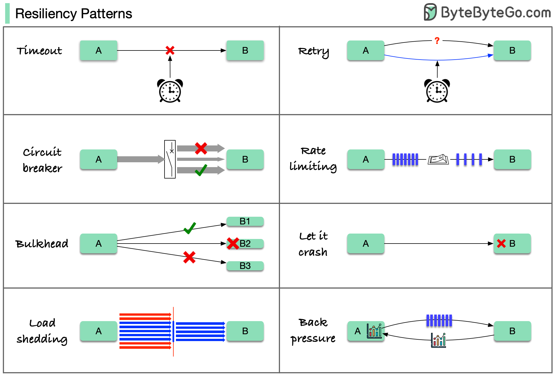
| Signal | Response | Failure contained | New cost |
|---|---|---|---|
| One call exceeds its latency budget | Timeout | Releases caller capacity and bounds tail latency | Can abandon work that still completes downstream |
| A safe operation fails transiently | Retry with capped exponential backoff and jitter | Hides brief transport or overload faults | Adds load and latency. Can duplicate unsafe writes |
| A dependency fails persistently | Software Architecture/Patterns/Resilience Patterns/Circuit Breaker | Stops repeated calls and lets the dependency recover | Fast failures during the open interval |
| One workload exhausts shared resources | Bulkhead | Preserves capacity for other workloads | Reserved capacity may sit idle |
| Incoming demand exceeds safe throughput | Software Architecture/Patterns/Resilience Patterns/Rate Limiting or load shedding | Rejects work before queues and latency grow without bound | Some valid work receives 429 or degraded service |
| Producer outruns consumer | Backpressure | Makes demand follow downstream capacity | Propagates slowdown or requires bounded buffering |
| Optional capability fails | Fallback or graceful degradation | Keeps the critical path available | Stale, partial, or lower-quality output |
“Let it crash” is a supervision choice. It works only when the failed unit is isolated, restart loops are bounded, state recovery is defined, and callers still receive a controlled outcome.
Map Mechanisms to Failure Domain and Recovery
Fault tolerance starts with the unit that can fail and the recovery objective:
| Failure domain | Mechanism | Continues during failure? | Recovery requirement |
|---|---|---|---|
| Process or instance | Multiple instances plus health-aware load balancing | Yes, if capacity remains and health checks remove the failed instance | Replace capacity and preserve request idempotency |
| Availability zone | Replicas spread across zones | Yes, if quorum and routing tolerate one zone loss | Rebuild replicas without overloading survivors |
| Region | Active-passive or active-active regional design | Depends on failover mode and data replication | Define RTO, RPO, DNS/routing convergence, and split-brain controls |
| Storage device | Mirroring, erasure coding, or replicated storage | Depends on redundancy level. RAID 0 provides none | Replace media and rebuild before another failure |
| Dependency overload | Admission control, queues, backpressure, and degradation | Critical functions can continue | Drain bounded work and restore optional features gradually |
| Software defect | Isolation, canary rollout, rollback, and feature flag | Only outside the affected blast radius | Stop rollout, revert safely, and preserve compatible state |
Replication can copy deletion or corruption, so it does not replace a backup. Monitoring detects trouble. Recovery still needs a mechanism. The design is credible only after the stated failure domain has been exercised and recovery time and data loss have been measured.